
Disclaimer: I am an experienced DIYer in car repairs, but not a certified professional. This guide is based on my personal experience and is intended for informational purposes only. Attempting this project is at your own risk. I am not responsible for any damage to your vehicle, OBD2 scanner, or any other unintended consequences that may arise from following these instructions. Proceed with caution and ensure you understand each step before proceeding.
Creating a custom adapter for your OBD2 scanner can be a useful skill, especially when dealing with vehicles that may not have a standard OBD2 port configuration. This guide will walk you through the process of setting up a sealed car adapter for your OBD2 scanner, allowing for a reliable connection for diagnostics and troubleshooting.
Tools and Parts You’ll Need
Before you begin, gather the necessary tools and parts. Having everything prepared will make the process smoother and more efficient.
- Wire strippers/cutters: Essential for preparing the wires for connection.
- Needle-nose pliers: Useful for handling small components and crimping connectors.
- Molex crimping tool (optional but recommended): Provides a professional and secure crimp for the connector pins. If unavailable, needle-nose pliers can be used with extra care.
- Soldering iron (recommended): Enhances the electrical connection and provides added durability, especially for thin wires.
- 4-Pin Connector: This connector will interface with your vehicle’s specific port. Ensure it is compatible with your vehicle’s connector type. (4-pin connector example; pin/wire size = 22-16AWG; insulation/seal size = 1.3-1.7mm)
- OBD-II Cable: This cable will connect to your OBD2 scanner. (OBD-II Cable example)
If you have spare automotive wire, you can purchase a female OBD-II connector separately and wire it directly to the 4-pin connector, potentially saving on costs. Ensure you select the correct wire gauge and connector pin sizes for compatibility.
Understanding the OBD-II Connector Wiring
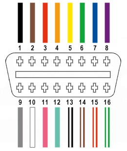
The standard OBD-II connector (OBD2C) has 16 pins, but for basic adapter functionality, we only need to focus on four essential wires:
- Pin 4 (Chassis ground): Provides the ground connection for the circuit (typically an orange wire on the specified OBD2 cable).
- Pin 6 (CAN [J-2234] High): Carries the CAN bus high signal for communication (typically a green wire on the specified OBD2 cable).
- Pin 14 (CAN [J-2234] Low): Carries the CAN bus low signal for communication (typically a brown wire with a white stripe on the specified OBD2 cable).
- Pin 16 (Battery power): Provides power to the OBD2 scanner (typically a green wire with a white stripe on the specified OBD2 cable).
Step-by-Step Guide to Building Your OBD2 Adapter
Follow these steps carefully to construct your OBD2 adapter.
1) Preparing the OBD-II Cable Wires
Start by preparing the OBD-II cable. Many guides recommend twisting pairs of wires to reduce electromagnetic interference and improve signal quality. To facilitate this, carefully remove the outer sheath and shielding from the OBD2C wires. Identify and separate the four wires you will be using (Pins 4, 6, 14, and 16 as listed above). Bundle the remaining 12 wires and secure them out of the way using a zip tie to keep your workspace tidy and prevent accidental shorts.
2) Preparing the 4-Pin Connector Pins
A common issue when using pre-made OBD2 cables is that the wire gauge (26AWG in this example cable) is often smaller than ideal for the pins of standard 4-pin connectors (typically designed for 22AWG). To compensate for this, we need to “thicken” the wire ends.
The wires from the OBD2C usually come pre-stripped with a short length of exposed wire (around 1/8″). Carefully strip off more insulation to expose approximately 3/8″ of wire. Fold this exposed wire back over itself, effectively doubling its thickness, and then twist the folded wire strands together tightly. This thicker wire will fit more securely within the 4-pin connector pins.
The 4-pin connector kit should include rubber seals. Slide one rubber seal onto each of the four prepared wires. These seals will provide environmental protection to the connection once assembled.
3) Attaching Wires to Connector Pins (Soldering & Crimping)
The pins for the 4-pin connector have two sets of prongs. The front prongs are designed to crimp onto the wire itself, while the rear prongs crimp onto the wire’s insulation seal.
Insert the exposed and thickened wire into the front of a connector pin, ensuring it aligns with the front set of prongs. You’ll notice that the wire might still appear small relative to the pin. Using needle-nose pliers to hold the wire firmly in place during the next step is highly recommended, especially given the small wire gauge.
At this stage, soldering the wire to the pin is strongly recommended. Soldering creates a robust and electrically sound connection, which is particularly beneficial when working with smaller gauge wires. If you are new to soldering, many online resources, like this helpful YouTube video on soldering techniques, can provide valuable guidance. Solder the wire to the pin, ensuring a good flow of solder for a strong joint.
If you have a Molex crimping tool, you can crimp the front prongs of the connector pin around the wire instead of soldering. If you don’t have a crimping tool, needle-nose pliers can be used as a substitute. Carefully and gradually fold one prong at a time over the wire, using the pliers at an angle to apply even pressure. This YouTube video on using pliers for crimping demonstrates the technique effectively. For added security, you can gently squeeze the prongs further with the pliers after crimping, though this may be considered optional.
4) Securing the Seal with Connector Prongs
Slide the rubber seal you placed on the wire up to the connector pin. Position the seal so it sits between the rear set of prongs on the pin. Using the same crimping technique as before (either with a crimping tool or needle-nose pliers), fold the rear prongs over the rubber seal. This secures the seal in place, providing strain relief and environmental protection for the wire connection.
5) Wire Pairing and Twisting (Recommended)
While not definitively proven to be necessary, many DIY guides recommend pairing and twisting specific wires to minimize potential interference. Pair the wires as follows:
- Pin 4 (orange) / Pin 16 (green w/white stripe)
- Pin 6 (green) / Pin 14 (brown w/white stripe)
Gently twist each pair of wires together. This step is believed to improve signal integrity, although its actual impact in this application is not rigorously documented.
6) Inserting Pins into the 4-Pin Connector Housing
Finally, insert the prepared pins into the 4-pin connector housing (4PC) in the correct orientation. Refer to the diagram below for the proper pin placement:
- Pin 14 (brown w/white stripe) > Connector slot A
- Pin 6 (green) > Connector slot B
- Pin 16 (green w/white stripe) > Connector slot C
- Pin 4 (orange) > Connector slot D
Insert each pin from the rear of the connector housing until it clicks into place. You should hear an audible click indicating that the pin is securely locked. Using needle-nose pliers can be helpful to gently pull on the wire from the rear to ensure the pin is fully seated and locked.
Completion and Testing
Congratulations! You have now assembled your DIY OBD2 adapter.
Before using your adapter for critical tasks, it is highly recommended to test it. In the original guide, the adapter was successfully used to read and clear a self-induced error code.
If any step is unclear or you encounter difficulties, re-read the instructions carefully and consider consulting online resources or seeking assistance from experienced individuals. Remember to always prioritize safety and double-check your connections before using the adapter with your vehicle’s diagnostic system.