
Have you ever experienced frustrating electrical problems in your car, like flickering headlights, malfunctioning sensors, or unexplained battery drain? Pinpointing the source of these issues used to be a complex and time-consuming task. However, with the advent of Digital Car Circuit Scanners, diagnosing automotive electrical problems has become significantly more accessible, even for those with limited experience.
This guide will delve into the world of digital car circuit scanners, explaining how they work and how you can effectively use one to troubleshoot electrical problems in your vehicle like a seasoned expert. Whether you’re a seasoned mechanic or a car owner looking to save on repair costs, understanding and utilizing a digital car circuit scanner is a valuable skill in modern automotive maintenance.
What Is a Digital Car Circuit Scanner Diagnostic Tool?
A digital car circuit scanner diagnostic tool is a specialized electronic device designed to quickly and accurately identify electrical faults within your car’s complex wiring system. Imagine it as a sophisticated multimeter combined with intelligent diagnostic software, specifically tailored for automotive circuits.
Think of your car’s electrical system as a vast network of roads, with wires acting as pathways for electrical current. Just like traffic jams can occur on roads, electrical problems can disrupt the flow of current in your car’s circuits. A digital car circuit scanner acts as a traffic monitor, allowing you to see where the flow is disrupted, whether it’s a blockage (open circuit), a shortcut (short circuit), or insufficient voltage.
Modern vehicles are heavily reliant on electrical components, from crucial engine sensors and control units to comfort features like infotainment systems and power windows. These components are interconnected by intricate circuit networks. Manually tracing wires and using trial-and-error methods to diagnose electrical issues in such complex systems can be incredibly challenging and inefficient.
A digital car circuit scanner simplifies this process by performing various tests, including voltage measurements, continuity checks, and signal tracing. This provides a clear and precise picture of the electrical system’s health, helping you pinpoint the exact location of faults quickly and efficiently. Instead of blindly searching, you can use the scanner to illuminate the problem area, saving you valuable time and effort.
Key Features and Functions of a Digital Car Circuit Scanner
To effectively utilize a digital car circuit scanner, understanding its core features and functions is essential. While specific capabilities may vary between models, most scanners offer these fundamental functions:
-
Voltage Testing: This feature measures the electrical potential difference in a circuit, essentially checking if the circuit is receiving the correct amount of electrical “pressure.” Think of it like checking the water pressure in your home’s pipes. Too low voltage can indicate a weak power supply or excessive resistance, while excessively high voltage could point to overcharging or regulator issues. A digital car circuit scanner provides real-time voltage readings, allowing you to identify voltage drops or spikes that can signal problems.
-
Continuity Testing: Continuity testing verifies whether an electrical circuit is complete and unbroken, meaning there is a continuous path for electricity to flow. Imagine a string of Christmas lights – if one bulb is broken or a wire is cut, the entire string might fail. Continuity testing helps you find that “broken bulb” or “cut wire” in your car’s circuits. The scanner sends a small test current through the circuit and checks if it returns, indicating a complete path. A lack of continuity signifies an open circuit, which could be due to a broken wire, a loose connection, or a faulty switch.
-
Short Circuit Detection: Short circuits occur when electricity deviates from its intended path and takes a “shortcut” to ground, often due to damaged insulation or wiring. This can cause excessive current flow, overheating, and potentially damage components or even start a fire. Digital car circuit scanners with short circuit detection capabilities can help locate these unintended pathways. They often use resistance measurements or signal tracing to pinpoint the area where the short circuit is occurring, allowing for targeted repairs without blindly searching through the entire wiring harness.
-
Signal Tracing: This function allows you to follow an electrical signal from its origin to its destination, much like following a breadcrumb trail. This is particularly useful in complex circuits where you need to verify if a signal is reaching a specific component or if it’s being interrupted along the way. Signal tracing helps identify breaks in the signal path, faulty switches, or damaged wires that are preventing proper communication between electrical components. Advanced scanners may even display the signal waveform, providing further insights into signal integrity.
Each of these features plays a distinct role in diagnosing various electrical problems. Familiarizing yourself with these functions is the first step towards becoming a proficient automotive electrical troubleshooter.
Step-by-Step Guide to Using a Digital Car Circuit Scanner
While the specific steps may vary slightly depending on the model of your digital car circuit scanner, the general process remains consistent. Let’s outline a step-by-step guide to effectively use a scanner for diagnosing electrical issues in your car.
For illustrative purposes, we’ll consider a scanner with features similar to the Foxwell GT60 (mentioned in the original article), known for its user-friendly interface and comprehensive diagnostic capabilities. However, these steps are broadly applicable to most digital car circuit scanners.
Step 1: Preparation and Connection
Before starting any diagnostic procedure, ensure your digital car circuit scanner is adequately charged or connected to an external power source, especially for extended diagnostic sessions. Many scanners have large color touchscreens that can consume significant battery power.
Locate your vehicle’s OBD-II (On-Board Diagnostics II) port. This port is standardized and typically located under the dashboard on the driver’s side. Consult your vehicle’s owner’s manual if you are unsure of its exact location.
Connect the OBD-II cable from your digital car circuit scanner to the OBD-II port in your car. Once connected, turn on the scanner. Most modern scanners will automatically recognize your vehicle’s make, model, and year via the OBD-II connection, streamlining the setup process and ensuring accurate diagnostics. Some scanners may require manual vehicle selection if automatic identification fails.
Step 2: Selecting the Appropriate Diagnostic Mode
Digital car circuit scanners offer various diagnostic modes tailored for specific tests. Choosing the correct mode is crucial for efficient and accurate diagnosis. Common diagnostic modes include:
-
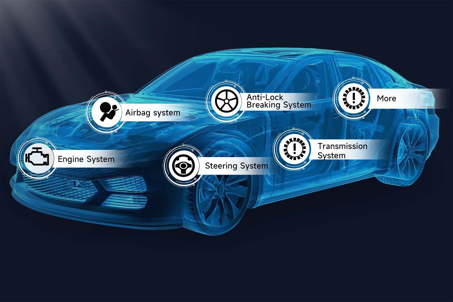
Full System Scan: When the nature of the electrical issue is unclear, initiating a full system scan is a good starting point. This comprehensive scan checks all major vehicle systems, including the engine control unit (ECU), transmission control unit (TCU), anti-lock braking system (ABS), body control module (BCM), and more, for any stored Diagnostic Trouble Codes (DTCs) and electrical anomalies. It provides an overall snapshot of your car’s electrical health and flags potential areas of concern for further investigation.
-
Voltage Testing Mode: To diagnose issues related to power supply or voltage drops in specific circuits, select the voltage testing mode. This mode allows you to measure real-time voltage readings at various points in the circuit using the scanner’s probes. Healthy circuits typically show voltage readings within a specified range (e.g., 12-14 volts when the engine is running). Deviations from this range, such as significant voltage drops or fluctuations, can indicate problems like poor connections, faulty wiring, or battery issues.
-
Specialized Module Testing: When you suspect an electrical problem is isolated to a particular system or module, such as the BCM or ECU, digital car circuit scanners often allow you to perform targeted tests on individual modules. This focused approach can pinpoint faults within complex systems more accurately and efficiently than a general system scan. For example, if you suspect a problem with your car’s lighting system, you might choose to specifically test the BCM, which often controls lighting functions.
Step 3: Reading and Interpreting Diagnostic Data
After selecting the appropriate test and running it, the digital car circuit scanner will display diagnostic information on its screen. While the initial display of data might seem overwhelming, modern scanners are designed with user-friendly interfaces to simplify data interpretation. Here’s what to focus on when reviewing the diagnostic data:
-
Voltage Readings: In voltage testing mode, the scanner will display voltage levels at the points you are probing. As mentioned earlier, compare these readings to expected voltage ranges for healthy circuits. Low voltage readings can indicate resistance, poor connections, or a weak power source. High voltage readings might suggest overcharging or voltage regulator issues.
-
Diagnostic Trouble Codes (DTCs): DTCs are standardized codes used to identify specific faults within vehicle systems. The digital car circuit scanner will display any stored DTCs along with descriptions to help you understand the nature of the problem. For example, a DTC like “P0300” indicates random engine misfires, while “B1000” might point to a fault within the BCM. Refer to a DTC lookup resource (many scanners have built-in databases) to get detailed information about each code and potential causes.
-
Freeze Frame Data: When a DTC is triggered, the digital car circuit scanner often captures “freeze frame” data. This is a snapshot of sensor readings and engine parameters (like engine temperature, RPM, and load) at the moment the fault occurred. Freeze frame data provides valuable context and can help you understand the conditions under which the problem arose, aiding in diagnosis and repair.
Step 4: Saving and Reviewing Results
Many digital car circuit scanners offer the ability to save diagnostic reports. This feature is incredibly useful for:
-
Tracking Intermittent Issues: If you are dealing with an intermittent electrical problem that doesn’t always trigger DTCs, saving reports over time can help you identify patterns and correlate symptoms with scanner readings.
-
Sharing Information with Mechanics: If you need to seek professional help, you can share saved diagnostic reports with your mechanic. This provides them with valuable information about the electrical issue, potentially speeding up the repair process and reducing diagnostic costs.
-
Documentation for Vehicle History: Keeping a record of diagnostic reports can be beneficial for your vehicle’s maintenance history, especially when selling or trading in your car.
By following these steps and familiarizing yourself with your digital car circuit scanner’s features, you can effectively diagnose a wide range of automotive electrical problems, saving time, money, and frustration.
Common Examples and How to Detect Circuit Issues
A digital car circuit scanner like the GT60 (or similar models) can be instrumental in identifying and diagnosing various common electrical system problems in your car:
-
Blown Fuse: Fuses are safety devices designed to protect circuits from overcurrent. When excessive current flows through a circuit, a fuse will “blow” (melt its internal wire), interrupting the circuit and preventing damage. Using the short circuit detection mode or continuity testing, a digital car circuit scanner can quickly help you identify a blown fuse. Continuity testing across the fuse terminals will show no continuity if the fuse is blown. Some scanners also have overload indicator lights or features that can further pinpoint the source of the overcurrent condition that caused the fuse to blow.
-
Loose or Corroded Connections: Loose or corroded electrical connections are a common cause of electrical problems in vehicles. Corrosion and looseness increase resistance in the circuit, leading to voltage drops, intermittent malfunctions, and even complete circuit failures. Using the voltage testing mode, a digital car circuit scanner can detect voltage drops across connections. By probing points before and after a connection, you can identify if a significant voltage drop is occurring, indicating a potential problem with the connection. Visually inspecting connections for corrosion is also crucial.
-
Short Circuits: As discussed earlier, short circuits are unintended pathways for electricity to ground. Manually locating short circuits can be a time-consuming and frustrating task. However, a digital car circuit scanner with short circuit detection capabilities significantly simplifies this process. By performing a full system scan and monitoring for abnormal current flow patterns or using specialized short circuit tracing modes, you can narrow down the area where the short circuit is likely occurring. Some scanners can even inject a signal into the circuit and allow you to trace it with a probe to pinpoint the exact location of the short.
-
Damaged Wires: Frayed, cracked, or broken wires can impede the flow of electricity and cause circuit malfunctions. The continuity test function of a digital car circuit scanner is ideal for checking wire integrity. By performing a continuity test on a suspected wire, you can determine if it is intact or has a break somewhere along its length. No continuity indicates a broken wire that needs to be repaired or replaced.
Learning to recognize these common scenarios and how to use your digital car circuit scanner to diagnose them empowers you to tackle many car electrical issues effectively.
Safety Tips and Precautions When Utilizing a Diagnostic Tool
Working with automotive electrical systems requires caution. While digital car circuit scanners are designed to be relatively safe, it’s essential to follow these safety tips and precautions:
-
Turn Off the Car When Possible: Unless the diagnostic procedure specifically requires the car to be running (e.g., testing charging system voltage), always turn off the ignition to minimize the risk of electrical shocks or accidental short circuits.
-
Wear Protective Gear: When working around the car’s battery or electrical system, it’s advisable to wear safety glasses to protect your eyes from potential sparks or battery acid. Gloves can also provide protection against minor electrical shocks and battery acid.
-
Work in a Dry Environment: Water and electricity are a dangerous combination. Always ensure you are working in a dry environment when using a digital car circuit scanner or working on any part of your car’s electrical system.
-
Double-Check Connections: Before applying power or starting any tests, double-check that all connections are secure and correctly placed. Incorrect connections can damage both the scanner and your car’s electrical system. Refer to your scanner’s manual and your vehicle’s wiring diagrams (if available) to ensure proper connections.
Practicing these safety measures will significantly reduce the risk of accidents and equipment damage when working with your digital car circuit scanner.
Troubleshooting Common Issues with Scanners
Even with the best tools, you might occasionally encounter issues while using a digital car circuit scanner. Here are some quick troubleshooting tips for common problems:
-
Scanner Won’t Turn On: First, verify that the scanner is adequately charged or properly connected to an external power source. If you are powering it from the car’s OBD-II port, ensure your car battery is not critically low, as some scanners draw power from the OBD-II port. Try connecting it to a different power source (e.g., a USB power adapter) to rule out a battery issue.
-
No Readings Displayed: Ensure that the probes are making good contact with the circuit points you are testing. Check that you have selected the correct diagnostic mode on the scanner for the test you are performing. Try restarting the scanner and re-establishing the connection to the vehicle’s OBD-II port.
-
Erratic or Fluctuating Readings: Loose connections are often the culprit for erratic readings. Double-check all probe connections and ensure they are making solid contact. Clean any corroded terminals or connectors. If the problem persists, there might be an issue with the scanner’s probes or internal circuitry.
These quick fixes can often resolve common scanner issues and get you back to diagnosing your car’s electrical problems.
Glossary of Key Terms in Car Circuit Diagnostics
To better understand the outputs and terminology used with digital car circuit scanners, here’s a glossary of key terms:
-
Voltage (V): The electrical potential difference or “pressure” that pushes electrons through a circuit. Measured in volts.
-
Current (Ampere – A): The rate of flow of electrical charge through a circuit. Measured in amperes (amps).
-
Resistance (Ohm – Ω): The opposition to the flow of electrical current in a circuit. Measured in ohms. High resistance reduces current flow.
-
Continuity: The presence of a complete and unbroken path for electrical current to flow in a circuit.
-
Short Circuit: An unintended pathway for electrical current to ground, bypassing the intended circuit path and often causing excessive current flow.
Understanding these basic electrical terms will enhance your ability to interpret the data provided by your digital car circuit scanner and diagnose electrical problems effectively.
Additional Resources for Learning Car Circuit Diagnostics
If you’re eager to deepen your knowledge of car circuit diagnostics and become even more proficient with your digital car circuit scanner, numerous resources are available:
-
Online Automotive Courses: Platforms like Coursera, Udemy, and Skillshare offer courses on automotive electrical systems and diagnostics, ranging from beginner to advanced levels.
-
Automotive Forums and Online Communities: Online forums dedicated to car repair and diagnostics are excellent places to ask questions, share experiences, and learn from other enthusiasts and professionals.
-
YouTube Tutorials: YouTube is a treasure trove of video tutorials on car electrical diagnostics. Channels dedicated to automotive repair often provide step-by-step guides and demonstrations of using diagnostic tools.
-
Vehicle-Specific Repair Manuals: For in-depth information about your specific car model’s electrical system, consult a vehicle-specific repair manual (e.g., Haynes, Chilton). These manuals often include wiring diagrams and detailed troubleshooting procedures.
Conclusion
Utilizing a digital car circuit scanner like the Foxwell GT60 or similar tools can revolutionize the way you approach automotive electrical diagnostics. No longer do you need to be an electrical expert to troubleshoot common electrical problems in your car.
By understanding the functions of a digital car circuit scanner, following a structured diagnostic procedure, and choosing the appropriate testing modes, you can effectively diagnose electrical issues, saving yourself time and money on potentially expensive mechanic visits. Furthermore, mastering the use of a digital car circuit scanner empowers you with valuable knowledge and confidence to tackle future electrical challenges that may arise in your vehicle. Keep your car’s electrical system running smoothly and reliably by embracing the power of digital car circuit scanners!
FAQs
Can you leave an OBD2 scanner plugged in while driving?
Yes, in many cases, you can leave a digital car circuit scanner (OBD2 scanner) plugged in while driving. Many drivers do this to monitor real-time vehicle data, such as engine temperature, speed, and sensor readings. However, ensure the device is securely mounted and positioned so it does not obstruct your driving or become a distraction. Some scanners are designed for continuous monitoring, while others are best used for periodic checks. Consult your scanner’s manual for specific recommendations.
Does OBD2 work when the car is off?
Generally, no, most OBD2 functions of a digital car circuit scanner require the car to be at least in the “accessory” mode (ignition turned to the first position) or with the engine running to read live data and perform comprehensive diagnostics. The OBD-II port typically receives power only when the ignition is at least in accessory mode. Some basic functions, like reading stored DTCs (depending on the scanner model), might be possible with just accessory power, but for live data and most diagnostic tests, the car needs to be at least in accessory mode or running.
What problems can the OBD2 detect?
A digital car circuit scanner utilizing the OBD2 protocol can detect a wide range of issues related to vehicle performance and emissions. This includes problems with:
- Engine performance (misfires, fuel system issues, sensor malfunctions)
- Emissions control systems (catalytic converter efficiency, oxygen sensor faults)
- Transmission (transmission control module faults, solenoid issues)
- ABS (anti-lock braking system) and traction control systems
- SRS (supplemental restraint system – airbags)
- Body control systems (depending on vehicle and scanner capabilities)
- And many other electronically controlled systems in modern vehicles.
Essentially, any system that is monitored by the car’s computer and reports diagnostic information through the OBD2 protocol can be assessed using a digital car circuit scanner. This makes it a powerful tool for diagnosing a vast array of potential vehicle problems.