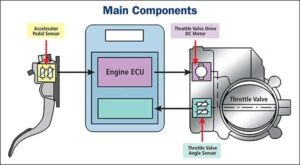
The accelerator pedal sensor (APS), also known as the throttle position sensor (TPS), is a critical component in your vehicle’s engine management system. It translates how far you press the gas pedal into an electrical signal for the engine control unit (ECU). A faulty APS can lead to poor acceleration, rough idling, or even engine stalling. This guide will show you how to test an accelerator pedal sensor with a multimeter, a crucial step in diagnosing potential issues.
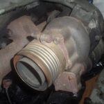
 Testing APP sensors with Multimeter
Understanding the Accelerator Pedal Sensor and its Function
The APS is typically located on the pedal assembly and connected to the gas pedal. It uses a potentiometer or a hall effect sensor to measure the pedal’s position. As you press the pedal, the sensor’s resistance or voltage output changes, signaling the ECU to adjust the throttle accordingly.
Common Symptoms of a Faulty Accelerator Pedal Sensor
Before diving into testing, be aware of the common signs of a failing APS:
- Hesitation or surging during acceleration: The engine may feel sluggish or respond unevenly when you press the gas pedal.
- Rough idling or stalling: The engine may run unevenly at idle or stall unexpectedly.
- Reduced fuel economy: A faulty APS can cause the engine to consume more fuel.
- Illuminated check engine light: The check engine light may turn on, often accompanied by a diagnostic trouble code (DTC) related to the APS.
Tools and Materials Needed for Testing
To test the APS with a multimeter, you’ll need:
- Multimeter: A digital multimeter is recommended for accurate readings.
- Vehicle repair manual: This will provide specific instructions and wiring diagrams for your vehicle model.
- Safety glasses and gloves: Always prioritize safety when working on your vehicle.
- Small flathead screwdriver: May be needed to disconnect electrical connectors.
Step-by-Step Guide on How to Test Accelerator Pedal Sensor with Multimeter
1. Locate the Accelerator Pedal Sensor: Consult your vehicle repair manual to identify the location of the APS. It’s usually mounted on the pedal assembly.
2. Disconnect the Electrical Connector: Carefully disconnect the electrical connector from the APS. Use a small flathead screwdriver if necessary.
3. Identify the Sensor Terminals: Your repair manual will show the wiring diagram for the APS. Identify the terminals for power, ground, and signal. Common configurations include three or five wires.
4. Set Up the Multimeter: Set your multimeter to measure DC voltage.
5. Test for Voltage: With the ignition key ON (engine OFF), connect the black lead of the multimeter to a good ground and the red lead to the sensor’s power terminal. You should see a voltage reading close to the battery voltage (around 12 volts). If not, there might be a problem with the power supply to the sensor.
6. Test the Signal Voltage: Connect the black lead to ground and the red lead to the signal terminal. Slowly depress the gas pedal. The voltage reading should smoothly increase as you press the pedal and decrease as you release it. A faulty sensor may show erratic readings, no change in voltage, or voltage outside the specified range (consult your repair manual for specific values).
7. Test for Ground: If you have a dedicated ground wire on the sensor, connect the red lead of the multimeter to the positive terminal of the battery and the black lead to the ground terminal of the sensor. You should have a reading near zero. A high resistance indicates a bad ground connection.
Interpreting the Multimeter Readings
- Smooth voltage increase/decrease: Indicates a properly functioning APS.
- Erratic voltage readings: Suggests a faulty sensor or wiring issue.
- No voltage change: Indicates a completely failed sensor or a broken wire in the circuit.
- Voltage outside specified range: Indicates a problem with the sensor or its calibration.
What to Do If the Test Indicates a Problem
If your testing reveals a problem with the APS:
- Check wiring and connectors: Inspect for damage, corrosion, or loose connections. Repair or replace as needed.
- Clean the sensor: Try cleaning the sensor with electrical contact cleaner.
- Replace the sensor: If cleaning and wiring checks don’t resolve the issue, the sensor likely needs replacement. Consult your repair manual for instructions on removing and installing the new sensor.
Conclusion
Testing the accelerator pedal sensor with a multimeter is a straightforward process that can help you diagnose common engine performance issues. By following this guide and interpreting the results correctly, you can determine if the sensor is the culprit and take appropriate action to fix the problem. Remember to always consult your vehicle repair manual for specific instructions and safety precautions.